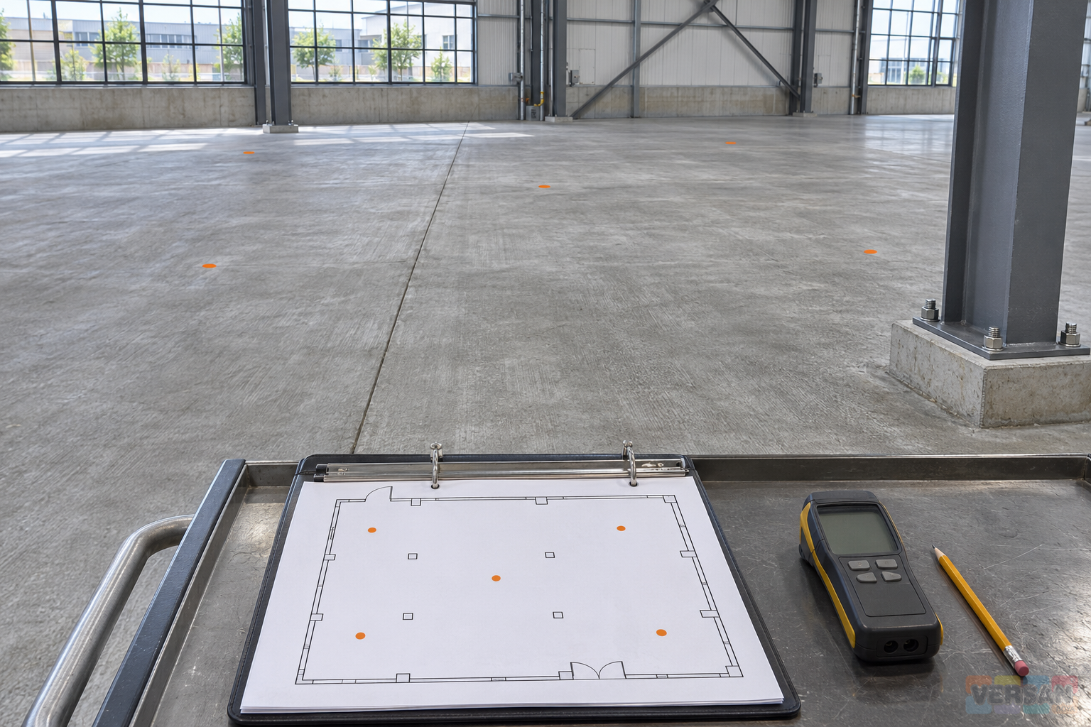
Make the floor plan an inspection record
A concrete floor can be primed across several bays while different decisions apply to each bay. A coating thickness result filed under a general room name may have come from a traffic lane, a repair strip or the narrow space behind a fixed machine. A number alone cannot tell the next shift where the primer was checked or whether the adjacent area was included. Put each result in a table linked to the floor plan. Give the result a location, a measurement method, an acceptance criterion and a decision status. That combination lets a supervisor see which part of the floor can be topcoated and where work must pause.
Start the inspection record with the floor level, a drawing revision, a defined work boundary and the coating stage. Choose an identifier that survives the inspection. If a record number changes every time a bay moves from inspection to repair and back again, the team will have trouble finding earlier readings. Use a consistent location identifier and attach successive visits to it. This is especially useful where professional coating systems are being applied in an occupied plant and different crews gain access to the same floor at different times. A location code makes the history usable when the original inspector is unavailable.
The catalogue entry for Nanomix Epoxyer primer describes a penetrating primer for concrete flooring and discusses trial areas for estimating absorption and consumption. Consider that distinction when setting up the inspection. The amount of material issued to a bay can be a useful check on coverage at an application stage. It cannot by itself establish dry film thickness above a porous substrate. A primer film may also be outside the useful range of an otherwise suitable instrument. Agree the physical quantity, the instrument or approved alternative and the required evidence for the selected system before priming the floor.
Anchor the drawing to fixed features
Show how the drawing is oriented and how the inspection team can find its starting reference on site. Use column grid lines, a permanent wall face or a designated construction joint. Avoid relying on a loose sign, a storage rack or a photograph that may have been taken from either end of the same aisle. A label such as ground floor, bay B4, east of the column, can take the reader to a reliable area. An additional offset or a close photograph can help the reader return to a particular measurement location. Use the same convention for repaired, excluded and inaccessible areas.
Distinguish the coating application boundary from the inspection area and the reading location. The boundary follows the staged work. An inspection area describes a part of the floor to which the sampling plan or check applies. A plotted point links to a recorded observation. Where a repair strip divides an original slab, the primer may have been placed during one shift across both surfaces. The specification may still call for separate examination of those substrates. Draw the transition and identify the two surfaces in the table. Reading the industrial coating systems section can help identify the product family to discuss when scoping the work.
Set out mandatory sample positions using the governing project procedure. Supplement them with separately identified investigation points when an unusual surface or a suspected local defect warrants another reading. Keep a check beside a drain, a repair boundary, a heavily trafficked crossing or a restricted access spot distinguishable from the normal sample population. When one point requires attention, the map should still show which surrounding locations were tested under the standard sampling rules. Reporting voluntary investigative readings as regular acceptance samples can change what the resulting average represents, especially where the investigatory points cluster around a single defect.
Define which layer and quantity the method measures
A reading taken after the primer has cured can refer to the dry thickness of a detectable film or, in some cases, the total thickness above an interface. A wet film check is a separate observation made at the application stage with a method selected for the surface. Consumption is a material balance and conveys no precise layer thickness on its own. Give each quantity its own field and unit. Before comparisons can be made, the project team should know where a measurement was taken, which of these quantities was recorded and whether a previous layer remained in that location.
Instrumentation must suit the coating and substrate. In the ultrasonic method described in DeFelsko's manual, a probe sends sound through couplant into the coating and the gauge interprets echoes from interfaces. Roughness and multiple interfaces can affect which echo is reported. Treat the expected range, the instrument model and its configuration as parts of the method. A successful reading on one test patch proves only what was demonstrated under those conditions. Before relying on the technique for an impregnating primer, confirm that it can resolve the intended layer at a representative location. The instrument manual explains how the gauge operates and the project documents govern acceptance.
A drawing may include the floor, a steel threshold and a neighbouring area that retains a previous coating. Mark where the substrate changes and what each measurement method is intended to measure. The catalogue lists Nanomix epoxy primer separately from its concrete floor primer. Approving one product for a defined use does not implicitly establish what is approved in the next bay. A film-thickness method and a criterion for a steel threshold may not apply to the concrete alongside it. Record the substrate and system beside the reading so the distinction remains visible when results are filtered or printed.
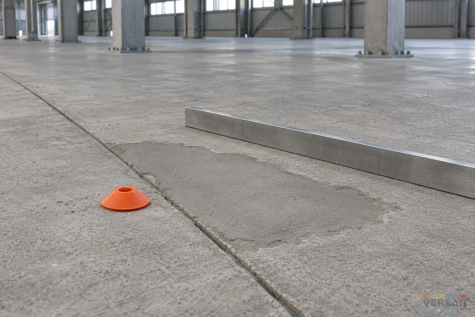
Keep the original readings and instrument configuration
Add the instrument identifier, probe type, configured unit and method revision to the inspection header. Record evidence of the relevant instrument verification and any setup used for the actual coating. A calibration certificate and a record of conditions on the day of use answer different questions. If the gauge or probe is changed halfway through a work area, record that change for the affected points. Where the method uses specific range or averaging settings, preserve the configuration that was used. This supports a later evaluation of whether readings from different shifts or pieces of equipment can reasonably be compared.
Log the raw values against the location and inspection time before applying any project-specific aggregation. If an unexpected reading is repeated, preserve the earlier entry and explain why the repeat was taken. A rough area, a probe seating issue or a location next to an interface change may be relevant context. Keep a reading with a method error separate from a valid reading that fails an acceptance criterion. For fixed references and point identity, the article on mapping repeat metal coating measurements offers a useful comparison. The floor plan adds the inspection area and a method suitable for the concrete system.
The instrument can also fail to return a usable result. Enter the actual condition, such as no usable reading, location inaccessible or method not approved here. A zero would be a different record. Document what is needed to close the gap. The technical team might review alternative evidence agreed in the inspection plan, for example a representative trial panel or an approved application record. Assess those options against the actual purpose of the check. A witnessed consumption record can establish what was used over a defined area. Another method would be needed to substantiate a specified film thickness unless the specification expressly provides for a different acceptance approach.
Trace the acceptance criterion to its source
Carry the current approved product data sheet and project specification references into each area record. Save the document date or revision with the criterion. For example, the archived p. 19 catalogue gives different entries for the penetrating concrete primer and the Nanomix Epoxyer topcoat. A film thickness accompanying a coverage example for a topcoat does not set a minimum dry film thickness for the primer. If two governing sources appear to disagree, resolve the discrepancy through the designated authority and record the agreed instruction before releasing the next coat. Refer to published data for the particular product, substrate and service conditions at issue.
Use separate columns for the observed value, the criterion and the disposition. A line marked accepted should allow a second reader to locate the correct governing requirement and see how the result was assessed. Where the specification defines a sample-level average, that average should link to the underlying readings and their sampling area. There may also be separate limits for individual readings. Identify the applicable rule without creating a new one. Epoxy paint products can have different roles within the build-up, so an approved change in the product should prompt a review of the affected measurement and intercoat requirements.
A satisfactory thickness assessment is only one part of the release record. Check the surface condition, elapsed time and other controls that govern the next coat independently. The public introduction to ACI's guide for concrete slabs under moisture-sensitive flooring explains that moisture is one criterion alongside other slab and joint conditions. No reading taken after priming can replace an outstanding moisture test or settle a joint detail. See epoxy primer surface checks before topcoating for the associated visual inspection. Link these independent decisions to the same floor area so that each remains traceable to its evidence.
Show evidence gaps and changed boundaries
A simple status convention can show areas released, areas awaiting correction, areas pending evidence and areas expressly excluded from the scope. Define those terms with the team before the drawing is used to assign work. Keep any temporary access restriction dated and linked to a named action. For example, a machine base may block access to part of an aisle. State which readings have been obtained and which need to wait until the bay is available again. Unmarked space on a floor drawing is open to interpretation. A clearly bounded pending area makes it easier for the incoming crew to keep the right section out of the topcoat sequence.
When a location is rechecked, compare the coating stage, the instrument method and what has happened to the surface since the previous visit. A reading added after a local repair may measure a different coating stack. If the original point was removed by the repair or cannot be accessed, record the relationship of the new position to the old one. Avoid entering a replacement location as if the exact point had been revisited. Where a self-levelling epoxy coating is later installed, keep the earlier primer review identifiable alongside subsequent system thickness records. A completed work stage can be useful evidence without representing the current physical state.
Retain former revisions and publish the updated plan with a short account of what changed. If a repair boundary extends beyond the original marks, the new limits should be shown next to the superseded limits and their affected readings. Identify any portion of the prior approval that still applies. Meeting notes, photographs and revised records should point to the same location codes. A new drawing without the change history can leave crews working from conflicting instructions. Where an industrial paint project runs through several shifts or shutdown windows, a dated map and a clear change note make it possible to account for each new release.
Release the next coat by verified area
If different areas were primed at different times, inspect and release them against the requirements that apply to each. Write the area boundary, applicable coating stage, time and authority for each decision. A release mark on a drawing should correspond to a recognisable boundary on the floor, so the installation team knows where to stop. Leave adjacent pending areas visible and identify their open items. A full-floor release might be inappropriate even when a large share of the readings are satisfactory. Remember that the route from one bay to another can also affect whether newly treated or restricted areas can be kept protected during work.
For an area held beyond its expected time window, refer to the guide to an exceeded epoxy primer recoat window and the applicable product instructions. The previous thickness assessment may remain useful history while the surface and elapsed time require a new decision. If the Nanomix epoxy topcoat or another planned finish changes, carry the decision back to the approved system documents. Record who confirmed compatibility and which zone the confirmation covers. Let the map show what the next crew may apply and where, with the evidence trail leading to the responsible reviewer.
Check the actual materials used as well. The existence of Nanomix epoxy thinner in the catalogue does not authorise it as an addition to any primer. For thinners and auxiliary materials, the system documents should specify suitability and any permitted amount. The instructions for a solvent-free penetrating primer should be followed as approved for that product. Connect the batch and mix records to the application area where the inspection plan requires that trace. If a change is under review, documenting both the affected material and the location is more useful than recording one without the other.
Leave a record the next shift can use
Give the receiving team a short map linked to the original inspection table. Include the drawing revision, system identity, substrate, instrument record and acceptance source. Put the point, date, value, method and status on each measurement entry. Make a summary of open actions with the location, check still needed and responsible party. A photo should help locate a point or explain a surface difference, and a revised reading should retain the earlier value and the reason for the update. At handover, ask a colleague who was not present during the initial inspection to identify one point on the drawing and find it on the actual floor.
Use catalogue names carefully when explaining the recorded layers. For instance, a clear epoxy coating and a visually similar penetrating primer may play different roles. The Versan Boya product range can help locate appropriate technical information, while project records identify the exact materials approved and used. The most useful final check is to verify that the drawing, readings, product revision and area release tell the same story. If an approved colour on the map obscures an unresolved measurement or surface issue, correct the record before handing the work area to the topcoat team.