Decide which comparisons the inspection must support
A dry film thickness record is most useful when a later inspector can connect each reading to the physical part and surface that produced it. A description such as “outside face” might make sense to the operator who has the part on the bench. After installation, repair or a shift change, more than one face can fit that description. A repeat inspection requires a stable way to establish orientation, identify the inspected zone and recover the original measurement conditions. Define this information at the first visit. Trying to reconstruct it from the readings alone creates uncertainty about whether an apparent difference reflects the coating or the location.
Projects that use industrial paint may call for routine acceptance measurements, targeted follow-up after a defect and additional readings after a repair. These activities can use a shared map with different entries for their purposes. An acceptance reading has to follow the applicable inspection plan. A follow-up reading is valuable when it can be matched to a particular prior observation. A diagnostic reading might be selected because an area looks different or is difficult to reach. Give each reading a purpose and retain it when exporting the report. A clean set of numbers is less informative when the reason each value was collected disappears.
Review the product and layer sequence while planning the map, even when measurement is handled by a different team. The industrial coatings range includes products with different roles in a paint system. The inspector needs to know whether the work order calls for a reading after a primer, after an intermediate operation or after completion of the specified system. Use the work order and technical documents to establish the stage. If future access will be restricted by assembly, record which zones must be examined before assembly and which will remain available for later follow-up. That practical step makes the map useful throughout the job.
Give the map a reference frame that survives handling
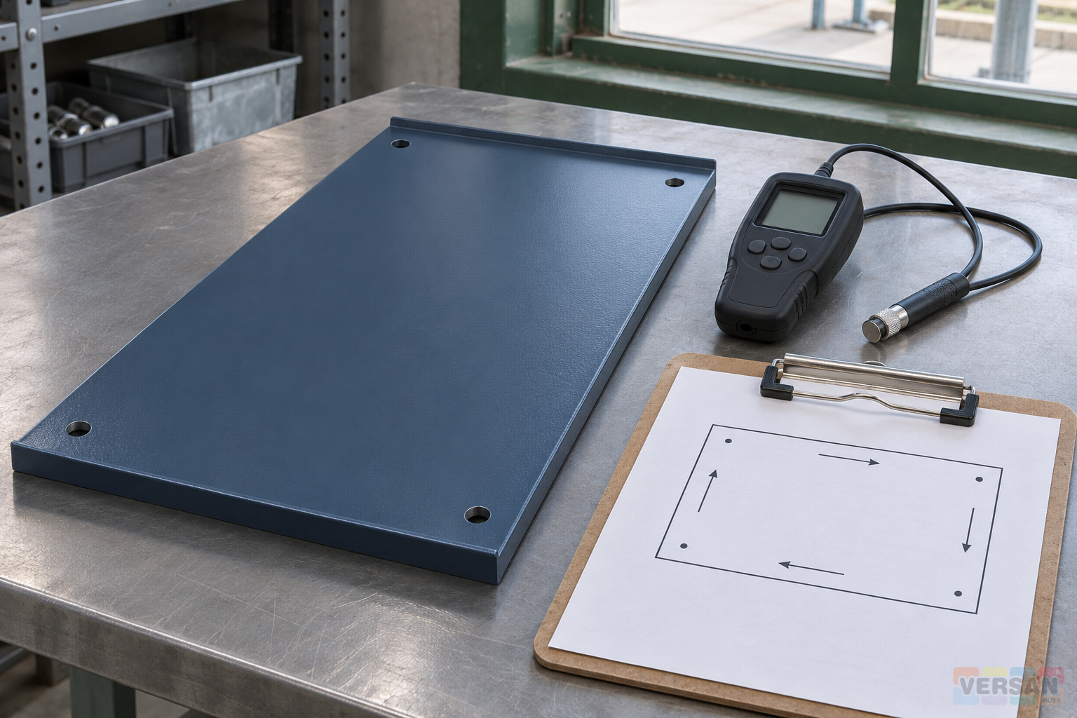
Start with a clear general view of the part. Identify an orientation feature that can be recognized after the part has been taken off the jig or turned over. A lug on one side, an asymmetric hole pattern or a return flange can provide that reference. Name each face and show the viewing direction. A general photograph helps establish scale and orientation. A second photograph from a suitable angle can show which face is visible and how the part is set down. Give both photographs a reference so the person using the map knows which region of each view corresponds to the drawing.
Use point identifiers that a second inspector can reproduce. Match a simple code to the part identifier and the face or zone. Give the code a location description tied to recognizable features. The drawing may do most of the work on a straightforward part, while a close-up can show how to approach a more crowded area. Avoid relying on the direction the original operator faced or on a temporary packing label. The same part can return on a different bench, with its original temporary marks removed. The permanent features should still provide enough information to recover the target region.
If the same map will be used for a series of identical parts, record the physical part or traceable batch to which each reading belongs. Following a replacement part with the same model number is different from following an individual part through an intervention. Keep that relationship explicit in the worksheet. When a drawing changes, preserve the old identifiers and add a new revision instead of quietly moving a point. Reviewing the map during first sample approval for an industrial coating can expose ambiguous face names and inaccessible locations before the same problem repeats through production.
Separate the reference point from its set of readings
A map point defines where to return. The inspection method defines how readings are taken and how they are combined when a group is required. A report can retain a stable point identifier alongside the individual values, their unit and any summary generated under the applicable procedure. If the earlier file contains only summaries and the new file contains individual readings, identify that difference before making a direct comparison. A meaningful comparison requires that the two data sets describe the same thing. A label such as “mean” should state which values it summarizes and how they are attached to a location.
Mark geometric transitions wherever they affect access or interpretation. A broad flat face can be treated as a different zone from a flange radius, weld vicinity or edge. The guide to edge and weld inspection in metal coating covers checks relevant to those features. The map carries the location identity into later visits. A point where a probe cannot be seated appropriately should be flagged with the reason. If the applicable method calls for another probe or a different position, show that choice in the record. A convenient value from the flat face cannot establish what was measured on an inaccessible joint.
Try the location descriptions with a colleague who did not create the map. Ask them to identify each point in order and note which landmarks they use. Spot the locations where the first and second operators interpret the instructions differently, then clarify the map. Include a photo of a difficult approach when a written direction alone is insufficient. Avoid applying temporary markers or templates to the finished surface unless the project allows it. The goal of this exercise is to test the map and the intended access. The reading pattern, sample size and acceptance limits remain governed by the project documents.
Capture instrument setup and the condition of the substrate
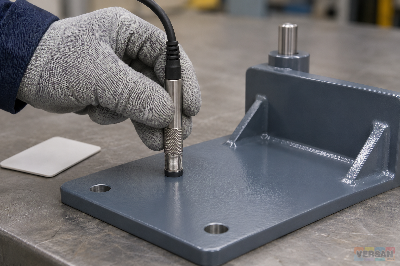
The DeFelsko PosiTector 6000 instruction manual describes three separate activities. Calibration is typically performed by the manufacturer. The user can verify accuracy with a known reference and may adjust a gauge for a specific surface in accordance with the applicable guidance. Inspection records should preserve the distinction. Write the gauge and probe identifiers, the traceable document where required, and the verification performed before use as separate entries. When a reference is used, keep its identifier and the outcome. Save the active adjustment or its reference where relevant. A record saying “calibrated” gives little basis for reconstructing which checks took place that day.
The same manual notes that substrate shape, composition and roughness can affect readings. An inspector who reaches the right point still needs to review how the measurement was made. Record the type of surface beneath the coating, the current part condition and the probe or setup used. A changed probe should bring its own documented verification. If a section has been blended during repair or if a new feature obstructs probe seating, record what changed. The displayed resolution is a gauge setting or capability. The ability to compare visits also depends on the method, the substrate and the condition at the selected location.
The archived NanoMix technical catalogue lists the NanoMix epoxy primer and NanoMix epoxy topcoat separately and relates a coverage example to dry film thickness. Use the current approved system documents and project specification for the acceptance requirements of the job. The epoxy paint range can help the purchasing or project team locate a product page, while the inspector uses the actual product code and application stage. A coating measurement taken after the full system is applied should be labelled for that stage. Plans that require separate layer records should schedule each appropriate inspection while that layer is available to measure.
Keep the production stages attached to the part history
The choice of coating, application stage and planned inspection can be recorded in the same system. A fabricated item that receives NanoMix epoxy shop primer may already have a thickness record when it moves to another station. When that part is later finished, refer to the original map and identify the new stage. This preserves the relationship without turning the new reading into an earlier primer reading. On jobs involving NanoMix antirust primer, preserve the exact product and stage labels so the audit can trace the work back to its order and specification.
On other orders, the manufacturing team might use NanoMix quick-drying industrial primer or NanoMix quick-drying industrial paint in accordance with the approved system. The industrial paint product listing can help clarify similar names during order review. Confirm the actual material with the approved work record. A map title such as “all finish readings” can hide whether a measurement was taken before or after an additional operation. Use stage descriptors that the coating team and the inspector both recognize and record changes in the work order as they occur.
Record the same information for work involving NanoMix polyurethane primer or NanoMix gloss polyurethane topcoat. Listing those materials together in an inspection guide does not establish a system recommendation. The inspection package should state the coating sequence approved for that particular part. A practical way to do this is to link the map to a controlled operation record containing the product identity and stage. Use the record to establish when a value can be taken under the relevant technical instructions. The report can then connect a result to the actual coating operation and the face that was measured.
Deal with missing and changed points openly
On a repeat visit, compare the part identity, face and map revision before resuming measurement. A flange behind a permanent fixture may disappear from the accessible surface, even though the part number is still correct. Record it as inaccessible and retain its earlier values. If a new point will be useful, assign it a new identifier, place it on the map and give the reason for measuring it. This makes the best use of the access available while preserving a clear record of what could actually be compared. Keep the reason near the reading instead of burying it in a general comment at the end.
When two values differ, work through the evidence before attributing that difference to application or repair. Confirm the underlying part, the point, coating stage, instrument and reference checks. A documented change in the inspection method may require the two sets to be reported separately. Where the procedure permits a recheck, retain the first result and log the new reading with its time and purpose. A supervisor exploring root causes of industrial coating defects can use this corroborated history alongside application records and observations. The history remains useful even when it leaves some uncertainty about the cause.
Consider a coated support where a repair was made around a mounting lug. An unchanged area on the broad face can be located with the original drawing references. A new reading at the boundary of the repaired region answers a different question about that region. The two readings can appear together if their purposes are marked. The inspector should record the repair extent, any changed substrate condition and the area from which the follow-up readings were taken. This makes it possible to review the results after the component is moved again, even if the visible repair boundary becomes difficult to identify.
Preserve the acceptance sample and the repeat evidence
For professional coating systems, a series of matched locations gives useful continuity between visits. Acceptance may require a wider selection of areas or an independent sample chosen under the governing procedure. Document that sample in the same project folder with its own location and selection records. A repeat measurement at a familiar point may support follow-up without covering the areas required for acceptance. Track the two purposes so an operational choice to revisit a known point does not remove a required sample. Where the quality plan changes, keep the relevant old and new revisions with their dates and scope.
Finish by testing whether the record can be read without a verbal briefing. It should lead a colleague from the work order to the part and map, then to the exact face, photos, point descriptions and original instrument readings. It should also show which readings were repeated successfully and which became unavailable or changed in purpose. Keep the date and repair or coating stage with every visit. If a later record uses different equipment, note the applicable verification and how comparability was assessed. A short, complete set of linked records makes a repeat check practical long after the original inspection team has moved on.