
A steel component can look well coated across its broad faces while its cut edges, weld undersides and connection corners present quite different application problems. Selecting a metal coating therefore involves more than choosing a product name and colour. Protection also depends on the condition in which fabrication reaches the coating team, and on when difficult details are inspected. Removing weld spatter after the finish has been applied creates a different scope of work from correcting the same detail before preparation begins.
This guide addresses the preventive stage: establishing an edge and weld control plan from fabrication drawings through coating acceptance. It does not investigate an existing corrosion failure, and it does not prescribe a universal grinding radius, film thickness or number of coats. The objective is to connect the project specification, current product instructions and the accessibility of the actual component. Fabricators, preparation operators, coating applicators and inspectors need a shared description of what is acceptable, who releases each stage and what evidence remains in the final handover file.
1. Start with fabrication review, rather than waiting for paint procurement
Edge and weld control should begin before the finished component arrives at the paint shop. Drawings can identify narrow corners, overlapping plates, closely spaced stiffeners and surfaces that will become inaccessible after assembly. Reviewing these features exposes areas that ordinary spray movements cannot reliably reach, and details that may require additional preparation or a different assembly sequence. The coating operation then becomes a planned production activity rather than a late attempt to overcome the limitations of completed fabrication.
The choice among industrial coating systems should be considered alongside this review. A system completed in a workshop faces different handling, waiting and access conditions from a system finished after erection on site. Link the drawing revision, fabrication batch and coating area so that changes remain traceable. The steelwork coating system specification guide provides a useful companion when translating product selection into a defined project scope. It helps keep the system description connected to the work actually being purchased and inspected.
2. Assess cut edges beyond whether they are free of burrs
An edge can be safe to handle without having the geometry required by the coating specification. Cutting method, sharpness, residual oxide and the available application direction deserve separate attention. A thin coating film at a sharp transition may not behave like the film on an adjacent broad face. Good appearance across the flat area therefore does not demonstrate equivalent protection at the edge. Edge preparation should have an acceptance point before coating obscures the original condition.
For iron and steel painting, define the required preparation in the project documents. A precise rounding dimension or preparation grade should come from the applicable specification and properly consulted standard, rather than an unsupported number taken from a general article. The work instruction needs to identify which edges are included, who checks them and where a rejected component returns in the production sequence. An approved representative component or photograph can improve communication between shifts, but it supplements the contractual technical criterion rather than replacing it.
3. Do not treat coating as a way to conceal unacceptable weld details
Weld areas may contain spatter, irregular transitions, cavities, restricted spaces or residues. These conditions do not all require the same correction. A preparation operator should not independently decide whether a weld is structurally acceptable. Details affecting coating should be referred to the fabrication and welding quality representatives, with the nature and location of the concern recorded. Applying more paint over a rejected weld does not complete fabrication acceptance and can make the original condition harder to examine.
Use specific language in the records. “Weld unacceptable” and “coating access restricted” indicate different decisions and responsibilities. Consistent coating terminology helps prevent a quality observation from becoming an ambiguous instruction. The public scope of ISO 8501-3 addresses preparation assessment for welds, edges and surface imperfections. The acceptance grade applicable to a particular project still requires the authorised standard, drawing and specification. A general guidance article cannot amend contractual inspection criteria or transfer the welding engineer's responsibilities to the coating inspector.
4. Separate geometric preparation from surface cleanliness
A corrected and ground weld is not automatically free from oil, dust or unsuitable residues. Conversely, apparently clean steel can retain a sharp edge or a projection that prevents sound coating application. Combining these assessments into a single “ready for paint” mark makes it difficult to establish what was actually checked. Record the acceptance of fabrication details first, followed by the surface cleanliness and profile required for the selected system.
Where an epoxy primer is being considered, suitability cannot be established from the appearance of clean metal alone. Read the current instructions for preparation, environmental conditions and application method together. Storage and possible recontamination after blasting or another preparation process also belong in the plan. If additional welding takes place after fabrication release, the earlier preparation record does not automatically cover the changed area. Local re-preparation and renewed inspection must be linked to the component revision, so the final file describes its actual history rather than the history of an earlier configuration.
5. Plan access to corners, flanges and surfaces that will be enclosed
Being able to see a corner does not mean a brush or spray gun can approach it at a suitable angle. Closely spaced stiffeners, connection plates and enclosed spaces may restrict working distance. When a required coated surface will disappear behind assembly, the fabrication sequence must make application and inspection possible beforehand. Responsibility for hidden surfaces needs to be explicit: becoming invisible is not evidence that the necessary protection has been completed.
Selecting a different product family, including a polyurethane primer, does not by itself solve an access problem. Evaluate pre-coated connections alongside welding, mating surface and assembly requirements with the responsible engineering team. Areas that must remain uncoated should be identified on the drawing; the applicator should not invent coating boundaries. An inspection hold point before access closes allows a decision without dismantling completed work. Photographs and release records from that stage become part of the handover evidence, particularly where later inspection can confirm only the exterior of the assembly.
6. Define stripe coating as a controlled part of the approved system
Stripe coating is an application step used to support local film continuity at edges, welds and complex details. It should not be assumed to use the same material, sequence or number of passes on every project. Specify the product, its position relative to the general coat, applicable recoating conditions and inspection method within the approved system. Seeing a brush pass across one weld does not establish that every required detail has been treated correctly.
With a system incorporating a two-component epoxy topcoat, verify mixing, usable working time and intercoat compatibility against current product information. Arbitrary thinning is not a substitute for a defined stripe coating procedure, and the general coat product should not automatically be assumed suitable for every local operation. Record component identity, material, batch, application time and the details covered. Undersides can be examined using an inspection mirror or another suitable access method. Released areas should remain identifiable so that assembly, subsequent coats or handling do not erase the evidence of what was checked.
7. Connect the coating sequence to workshop handling and assembly
A component may move between preparation, priming, intermediate coating, assembly and finishing several times. Every movement can introduce edge damage or contamination. A plan that describes only the first painting operation leaves uncertainty about exposed metal created during installation. Lifting points, temporary supports, handling contacts and packaging details should be communicated to the coating team before production begins. Those arrangements affect both protection and the later repair scope.
When a gloss polyurethane topcoat is selected, confirm that the preceding coat remains suitable and that its recoating conditions are satisfied. A clean final appearance does not make an underlying preparation deficiency acceptable. Additional welding or grinding after initial coating needs a defined repair system. State whether the repair is a finish touch-up or a process beginning with renewed preparation and the required underlying coats. This prevents different teams from proposing incompatible scopes for the same damage immediately before delivery, when access and time are often most constrained.
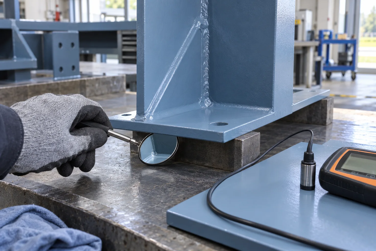
8. Distinguish flat-surface thickness readings from edge continuity
A gauge reading taken on a broad flat surface does not by itself represent a narrow edge or the underside of a weld. Probe contact and component geometry can influence a result. Consider the equipment manufacturer's limitations alongside the measurement procedure accepted by the project. Identify details where direct measurement is unavailable or where results require special interpretation. Obtaining a numerical value from an unsuitable location is not the same as obtaining defensible inspection evidence.
Using an acrylic primer or another binder family does not remove this geometric measurement issue. Thickness measurements should be accompanied by checks of visual continuity, difficult surfaces and application records. Explain where readings were taken and where direct measurement was not possible. Excessive local build-up or runs should not automatically be treated as superior protection; the approved system's film structure and defect criteria remain applicable. A representative sample can help establish a practical inspection method before production, particularly when the same restricted detail appears across a large batch of fabricated components.
9. Define inspection points that fit the production sequence
A plan that postpones every check until final acceptance may encounter surfaces that are no longer accessible. Instead, select appropriate inspection points after fabrication, after preparation, following stripe application and before a connection is closed. Define notification time, responsible inspector and whether work can continue without release. Witness points and mandatory hold points should be interpreted according to the project contract; their different consequences need to be understood by production personnel.
When considering products with particular production timing requirements, such as a quick-drying industrial topcoat, a demanding schedule must not justify missing inspection records. Enter the current drying and recoating conditions into the work programme. A catalogue description does not guarantee the same interval in every environment. Similar components may be grouped into inspection batches where the agreed quality plan allows it. The sampling scope and details requiring individual examination must nevertheless be established in advance, rather than reduced informally when an inspector or production team is under pressure.
10. Use a representative sample to verify the method, not only appearance
A flat colour panel may not establish whether a welded connection can be prepared and coated successfully. If production repeatedly includes a difficult detail, the representative sample should incorporate that geometry. Edge preparation, approach direction, stripe application and inspection sequence can then be assessed together. The approved example becomes a practical reference for how work is carried out, rather than a panel that represents only colour and gloss.
When comparing options in the coating product range, connect sample records to the exact product and system revision. A change of primer, finish or preparation method is not automatically covered by approval of the previous sample. Criteria established on the sample need to be transferable to the actual component. Success on a small, easily accessible panel does not demonstrate that an enclosed connection offers equivalent working conditions. Document the differences between sample and production geometry, and decide which additional checks or access measures are needed before the sample is treated as evidence for the production process.
11. Document the handover between fabrication, application and quality
Arrival in the coating area should not imply that all fabrication details have already been accepted. The handover record needs component identification, drawing revision, open nonconformities and areas deliberately excluded from coating. If an applicator begins work solely from the production programme, a fabrication deficiency may later be debated as though it originated with the coating team. A written release makes the responsibilities visible and provides a traceable basis for continuing work.
The industrial coating first-sample approval approach can support the transition from an assessed example to routine production. State exactly which details the approval covers. The quality representative, applicator and fabrication supervisor need access to the same document revision. If work continues with an open issue, record the authorised decision and its conditions. Verbal acceptance should not disappear between shifts. The final handover package should also show how surfaces that cannot be inspected after assembly were verified while access remained available.
Where photographs provide inspection evidence, connect each image to the component number and the area examined. An unidentified weld photograph does not show which of several similar components was accepted. Retaining an overall view alongside a close view of the relevant detail makes the scope clearer. Agree file naming and storage location so that the next shift can find the same information. When a nonconformity is corrected, retain the original observation and link the correction and renewed acceptance to it. The record then shows both the accepted result and the work that produced it. This makes quality documentation a traceable part of the production sequence, rather than a collection of images separated from the physical components.
12. Describe difficult-detail scope as clearly as material quantity
Two fabrications with the same overall metal area can have very different edge and weld workloads. Numerous small stiffeners, narrow corners or circumferential welds create preparation and application requirements unlike those of a flat plate. Comparing quotations only by square metres and paint kilograms may leave uncertainty about which party is responsible for the additional operations. Define the process scope alongside the quantities so that suppliers and contractors are pricing the same work.
When submitting a coating quotation enquiry, include drawings, component quantities, approximate area, edge and weld density, restricted access and the division between workshop and site work. Selecting products in the quotation basket does not itself approve the technical system or this execution scope; supporting details may be needed. Ask whether stripe coating, local preparation, post-assembly repairs and inspection documentation are included. Quotations can then be compared by the steps required to complete and accept the job, rather than by package price while important workmanship and verification activities remain undefined.
13. Bring revisions and repairs back into the original control plan
Additional holes, stiffeners or relocated connections can change a coating detail that had already been approved. Matching the repair colour to the old finish is not sufficient. Reassess the changed geometry, preparation method and access conditions. Link the fabrication revision and coating repair record to the same component identity, keeping the completed system understandable within the handover file. Without that connection, a drawing may describe one condition while inspection evidence relates to another.
If a defect has already appeared, the guide to early corrosion after antirust priming addresses evidence-led failure investigation. The preventive plan described here controls the sequence before a defect develops; the two approaches complement each other. Repair decisions require review of the existing film, damage boundary and material compatibility. The visible rust patch should not automatically define the entire treatment boundary. After repair, repeat the required checks and connect the new records to the original acceptance documentation, so the repaired condition is neither undocumented nor mistaken for untouched original work.
14. Turn the specification into a usable daily checklist
A detailed specification becomes more practical when supported by a working checklist. Include component identity, applicable drawing, fabrication detail release, preparation acceptance, stripe scope, system coats, inspection timing and outstanding issues. Each item needs a responsible person and a record location. The checklist then provides a basis for progressing to the next stage, rather than merely collecting signatures after production has already moved on.
- Are edges, welds and surfaces that will be enclosed identified on the drawing?
- Have fabrication detail acceptance and surface cleanliness been checked separately?
- Are stripe material, sequence and recoating conditions defined?
- Is there a suitable inspection method for details that cannot be measured directly?
- Are assembly damage and local repair records linked to the original system?
Use the technical enquiry and contact channel to establish project-specific requirements with current product documentation. Reliable protection is not achieved simply by asking for the thickest film or the greatest number of coats. It requires fabrication detail, the selected system and acceptance evidence to be managed together. Resolving access and preparation before painting offers a more defensible starting point than improvising touch-ups when the completed assembly is about to leave the workshop.
Technical sources and scope
- Nanomix epoxy technical catalogue archive: product-family reference, not a replacement for current application instructions.
- Nanomix polyurethane technical catalogue archive: archived system reference; project-specific compatibility requires confirmation.
- ISO 8501-3:2025 public scope: preparation assessment for welds, edges and surface imperfections.
- ISO 12944-1:2017 public scope: the protective paint system approach for steel structures.